so i have very dim lights, tail lights and blinkers and brake lights. i notice these 'circuit boards' they have are very primitive boards. when i plug in different lights in those boards things get brighter on the opposite board. are these wired in series all over the car? would it be a good idea to possibly get rid of the circuit board all together and just wire in plugs to the lights. do these boards go bad or is it the wiring itself that is a problem?
one last thing what is the brown wire fix? i couldn't quite get enough information to understand it.
circuit board woes
-
So Cal Mark
Re: circuit board woes
if the various bulbs change intensity as you turn others on and off, you're not getting good grounds. Very typical of those boards and sockets. Several people have drilled out the rivets and repaired the connections and replaced the sockets with good results
-
SpiderJim
Re: circuit board woes
I'm in agreement with mark. I just refurbished two pairs of these boards. One set of lights was not working. Biggest issue is the crap way they did the grounding at the socket base. I cleaned mine up and soldered a bridge wire between the socket body and ground plain. Just scrape off a bit of the trace covering then solder.
-
mipstien
Re: circuit board woes
i went and purchased all new tail lights today and a wire brush to clean out the terminals. picked up another multimeter cause i can't find mine *shrug*. anyways i checked the voltage coming into and out of the circuit board and it looks like its 9-10volts. shouldn't this be 12v?
but my problem is this. what i THOUGHT where the brake light, tail light, turn signal, reverse light (starting from top left read like a book on the circuit board) the bottom left(turn signal) is the thing getting dimmer and brighter when i press the brake pedal. on top of that its not very bright at all and only works on the left side of the car. the tail light or running light does come on when i turn the lights on but i sure as heck can't figure out why nothing else works. am i missing something? i found a wiring diagram and will look at it really good in the next few days but i sure could use some pointers on what in the world may be going on with this. i really can't for the life of me figure out how things are and aren't working when they should or shouldn't be.
but my problem is this. what i THOUGHT where the brake light, tail light, turn signal, reverse light (starting from top left read like a book on the circuit board) the bottom left(turn signal) is the thing getting dimmer and brighter when i press the brake pedal. on top of that its not very bright at all and only works on the left side of the car. the tail light or running light does come on when i turn the lights on but i sure as heck can't figure out why nothing else works. am i missing something? i found a wiring diagram and will look at it really good in the next few days but i sure could use some pointers on what in the world may be going on with this. i really can't for the life of me figure out how things are and aren't working when they should or shouldn't be.
-
mipstien
Re: circuit board woes
Any ideas? I'm thinking about direct wiring through the car for testing just run wires from battery to switches and back?
-
Foster48x
Re: circuit board woes
Hang in there mipstien! I had the same issues last summer with my tail light circuit boards. These guys told me the same thing they're telling you... bad grounds! and they were right. I of course was so confused with the wiring diagrams that I spent days testing all of the voltages coming in and out of the circuits and re-wiring the sockets that I thought were bad (but weren't). Through all of it I ended up overlooking a simple bad ground on a socket that I had failed to correct the first go around.
If I had to do it over I would have spent less time worrying about what the volt-meter was telling me and more time making sure the socket connections and grounds were clean and solid the first time. I think it would have saved me allot of heartache. In the end I had to bypass some of the bad copper strip with electrical wire, re-solder almost all of the sockets on the left board, and add an additional ground on the right rear tail light board. The additional wiring doesn't look pretty but it works.
Good luck!
Rick
-
mipstien
Re: circuit board woes
How did u ground it out? Got a picture to maybe point me in the right direction
-
Foster48x
Re: circuit board woes
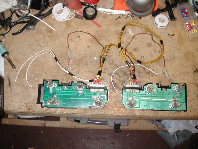
Here’s a pic of my rewired boards. The white wire on the right is the additional ground attached to the body of the car. Because some of the copper strip was damaged on the left board I bypassed the board entirely with the two white wires on the left. Both are hardwired into the wiring loom going into the left circuit board.
Cleaning the sockets where they rivet to the circuit board is important. The one that was giving me the most trouble looked like it was good, but had a bad connection. The rivet wasn’t making good contact with the brass strip on the circuit board. Also, if you solder any of the connections make sure to sand all of the coating off of the sockets and scrape/sand all of the coating off of the brass strips.
Hope this helps.
Rick
-
mipstien
Re: circuit board woes
well i soldered another ground basically the same place you did yours and all my lights started working again except for the blinkers. at one point the blinkers where working and now i get nothing so i think maybe while messing around with all the lights i might have knocked something loose for them in the wiring harness. so ill be working on that soon too now.
-
Foster48x
Re: circuit board woes
My blinkers also stopped working because of bad grounds on the boards.
Rick
Rick
-
mipstien
Re: circuit board woes
well i fixxed the ground. so mine looks like it might be something different? who knows though i got a lot to figure out still hehe
-
spider2081
- Patron 2024

- Posts: 3009
- Joined: Fri Jan 27, 2006 11:45 pm
- Your car is a: 1981 Spider 2000
- Location: Wallingford,CT
Re: circuit board woes
I have repaired with a few Printed Circuit assemblies. What I found is that the rivets holding the sockets and center contacts to the printed circuit board can look ok but develop resistance and cause dim or intermittent lights. I clean off the green coating from the PC board in the areas of the light sockets. clean the sockets where it contacts the board. Use a paste electrical approved solder flux and solder each connection that has a rivet to the PC board. This takes a larger solder iron to get enough heat on the light sockets for the solder to flow properly. Too much heat on the PC board will damage the board.
Be sure all the bulbs are the correct type other wise some will be brighter than others.
Be sure all the bulbs are the correct type other wise some will be brighter than others.
-
dantye

- Posts: 344
- Joined: Mon Nov 30, 2009 8:00 am
- Your car is a: all gone
Re: circuit board woes
Remember that soldering/re-soldering a circuit board will often pop the copper off of the board, so applying dielectric grease under these pops after they cool can help prevent future corrosion.
Also, breaks in the copper can be virtually invisible, so use an ohm meter or continuity checker to check each circuit on the board from connector to socket. The most problematic one on my 81 Spider was the feed-through conductor at the very bottom of the driver's side tail light circuit board. This conductor is both very narrow and subject to corrosion since any leaking water, condensation and pollution naturally drain to this bottom edge. (Poor electrical design in a FIAT - who knew? )
)
If this conductor on the driver's side board has an invisible break, the passenger side rear turn signal will not work, and the flashing speed of the front signal on the passenger side will be too fast, since the flasher is operating on only half the resistance load.
To repair it, I found it was best to solder a jumper wire from end-to-end of the conductor rather than just solder across the break in the very narrow copper conductor.
Also, breaks in the copper can be virtually invisible, so use an ohm meter or continuity checker to check each circuit on the board from connector to socket. The most problematic one on my 81 Spider was the feed-through conductor at the very bottom of the driver's side tail light circuit board. This conductor is both very narrow and subject to corrosion since any leaking water, condensation and pollution naturally drain to this bottom edge. (Poor electrical design in a FIAT - who knew?
If this conductor on the driver's side board has an invisible break, the passenger side rear turn signal will not work, and the flashing speed of the front signal on the passenger side will be too fast, since the flasher is operating on only half the resistance load.
To repair it, I found it was best to solder a jumper wire from end-to-end of the conductor rather than just solder across the break in the very narrow copper conductor.