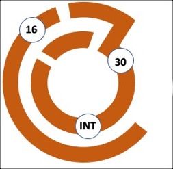
- in the 'OFF' position, both INT and 30 are connected
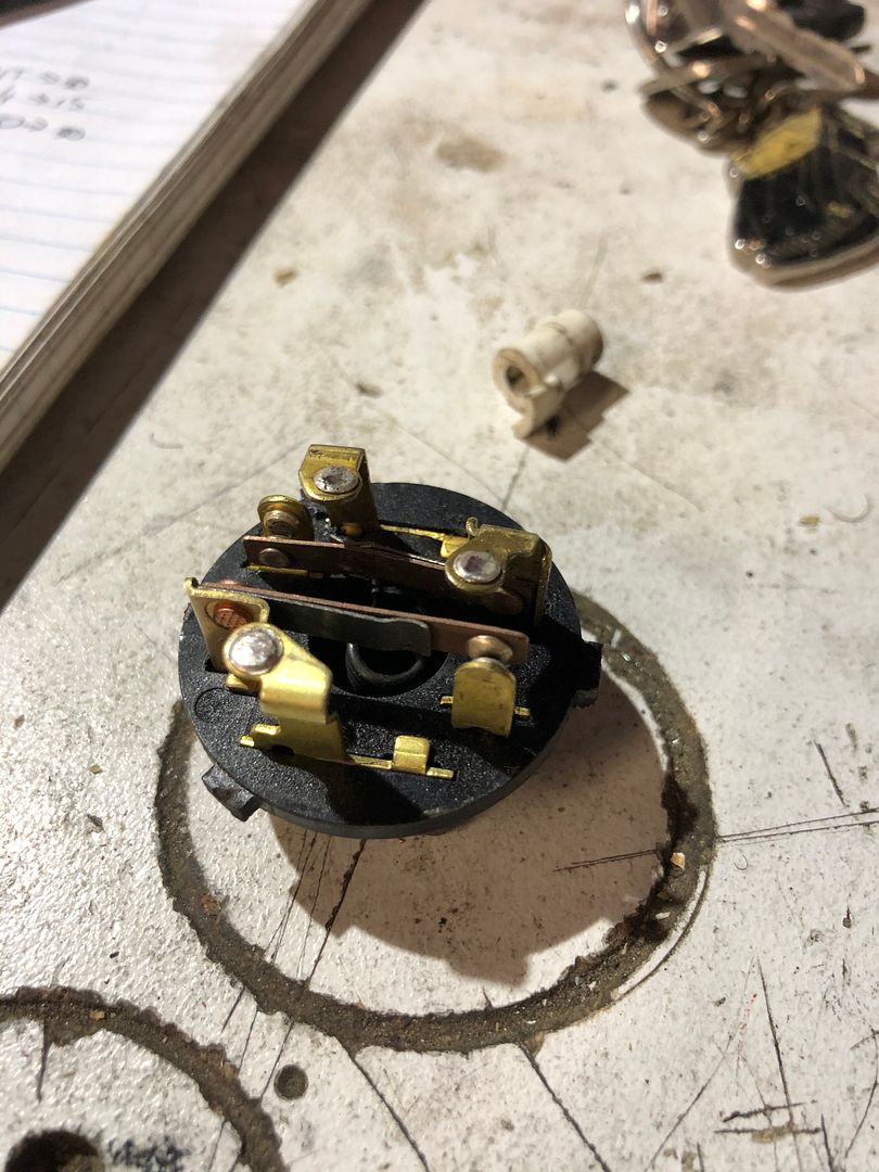
- in the 'RUN' position, INT and 30 are connected, and the 30/1 pin is connected to 15 (small contacts behind the terminals get connected together - hard to show in the photos, but will try and take another pic
- in the 'START' position, pin 50 is connected in to INT and 30
The contacts get made along this pathway:
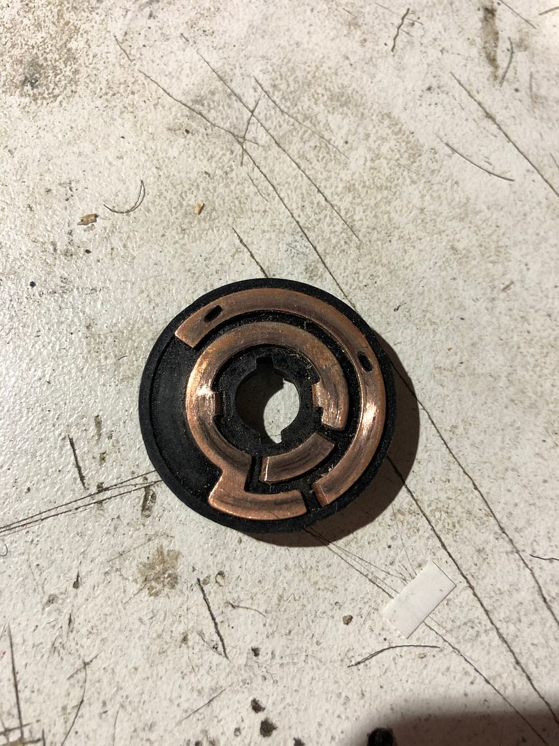
Here is the back of the ignition switch - same pin nos. ('16' x2, INT x 2, 30/1,50, 15, 30)
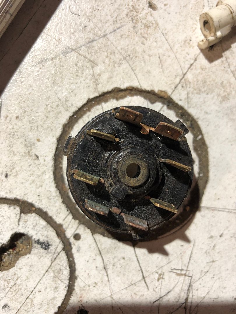
and a view of how the pins connecte to the copper pathway:
and my drawing of where the pins are in the 'OFF' position
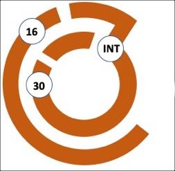
and the 'RUN' position; in addition two contacts close to connect pins 30/1 and 15; when you turn the key to START a second contact joins 50 to 30
