Turbo Hose Part 1
-
- Posts: 364
- Joined: Sat Dec 27, 2014 5:50 pm
- Your car is a: 1981 Spider
Turbo Hose Part 1
I'm attempting to get my '82 turbo up and running. After all the myriad other parts of the car to get sorted, I'm now starting in on one of the main bugbears of the turbo: the plumbing. The hose from the intake box to the turbo must rank as one of the singularly most idiotic ideas ever devised by humans (from Legend Turbos): In no space whatsoever it exists the turbo, bends 90 degrees, changes shape from circular to flattish oval, then makes another 90 degree turn and flares out to about 68mm. From this point it makes two more 90 degree bends: up and then out to the air box. Festival. Those hoses are no longer available (although rumor has it AR might produce turbo parts at some point).
To wit: how to make a turbo pipe. My ideas was originally to fabricate a metal part that would form the flat-oval between the turbo and the next 90 degree turn. Problem: no space in which to fit a silicone joint between a metal connection and the turbo. Spaces are that tight. So the whole thing has to be made of something else, something flexible, and thus, let me introduce you to my new friend: self-amalgamating rubber tape. Here is how I proceeded:
I used green floral foam (nasty stuff) to make the basic shape. You will see where this is going.
Then I used casting tape to make the basic shape. I thought casting tape would be it for the intake structure as the rubber tape is, well, rubber. But I had no idea how much heat the fiberglass casting tape could handle. So...
I cut open the casting tape form and removed the green foam model, then wrapped that in rubber tape. Wasn't sure quite how this would work out as the tape was so thin...but look at the original turbo hose: it is wrapped...something. So I kept going. This isn't the final version, there were some kinks to work out. I had an oblong shape along the back sticking out, and the larger curve was not quite the shape I needed to get to the other hoses. Rubber tape is astonishing: I cut out a bit, reshaped, then taped it up again, and it fused back together. Now it is thicker and stronger and stiffer enough to actually work as an intake hose. (The rubber is also rated at 500 degrees.)
(Footnote: I needed a back up plan so before I tossed the cut open casting tape form, I wrapped it with painters tape and filled it with plaster so I would have another mold if things did not work out with my plan.)
Okay, so now I've got the rubber bit for the lower part. Then it got easier. Two 68mm silicone elbows (from ebay) and two bits of muffler pipe flared slightly (from a local shop that was not nice to work with). Ended up with this:
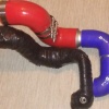
Here is what the finished bits look like next to the original:
My new rubber bottom hose is flexible enough to get shoved in past the wastegate and to be adjusted (with the exhaust tubing and clamps) so that I can avoid touching the firewall or anything else and get the elbows up to the intake airbox. (68mm, by the way, fits the airbox exactly.)
I have done a test fitting and it was pretty dang close, close enough that I'm going to install it and see how it holds up. Now the hang up is figuring out how to get the clamp onto the lower hose where it snugs onto the turbo...I mean, how to do that using a pair of human hands. There is just no room and I'm not sure how much shoving in I can/ought do.
Stay tuned for Part II of this exciting drama.
-
- Posts: 3798
- Joined: Fri Mar 15, 2019 11:23 pm
- Your car is a: 1969 and 1971 124 spiders
- Location: San Francisco Bay Area
Re: Turbo Hose Part 1
Looks like good work so far, Rodo, and I'm looking forward to hearing the rest of this epic saga. Especially the part where you get to slay some dragons, which in my mind is roughly equivalent to some Fiat repair jobs.rodo wrote:Stay tuned for Part II of this exciting drama.
I'm convinced that Fiat only hired workers with very small hands in some parts of the assembly process...
-Bryan
- RRoller123
- Patron 2020
- Posts: 8179
- Joined: Sun Nov 13, 2011 2:04 pm
- Your car is a: 1980 FI SPIDER 2000
- Location: SAGAMORE BEACH, MA USA
Re: Turbo Hose Part 1
Man, that is a lot of creative work right there!
'80 FI Spider 2000
'74 and '79 X1/9 (past)
'75 BMW R75/6
2011 Chevy Malibu (daily driver)
2010 Chevy Silverado 2500HD Ext Cab 4WD/STD BED
2002 Edgewater 175CC 80HP 4-Stroke Yamaha
2003 Jaguar XK8
2003 Jaguar XKR
2021 Jayco 22RB
2019 Bianchi Torino Bicycle
'74 and '79 X1/9 (past)
'75 BMW R75/6
2011 Chevy Malibu (daily driver)
2010 Chevy Silverado 2500HD Ext Cab 4WD/STD BED
2002 Edgewater 175CC 80HP 4-Stroke Yamaha
2003 Jaguar XK8
2003 Jaguar XKR
2021 Jayco 22RB
2019 Bianchi Torino Bicycle
-
- Posts: 1120
- Joined: Wed Mar 17, 2010 9:48 pm
- Your car is a: 1983 PININFARINA
- Location: Sherbrooke, Qc, Canada
Re: Turbo Hose Part 1
The hose fitting is for crankcase hose?
-
- Posts: 162
- Joined: Thu Aug 10, 2006 11:59 am
- Your car is a: 1981 Turbo Spider
Re: Turbo Hose Part 1
Yes, the usual port just ahead of the throttle body is pressurized when the turbo is spun up. The Turbo Spider uses a longer vent hose to reach the nipple on the end of the AFM duct just in front of the turbo intake.
-
- Posts: 2130
- Joined: Wed Dec 24, 2014 10:21 pm
- Your car is a: 1978 124 Spider with Isuzu Turbo Diesel
Re: Turbo Hose Part 1
Rube Goldberg would be proud!
The Turbo Plumbing on the Diesel is interesting too. The previous owner didn't even try to keep the original air box and put a Spector Cone Diesel Air Filter on and even that was a tight fit despite the flat box tube exhaust manifold bolted directly to the drivers side of the head with no feeder tubes at all. The turbo flange is parallel to the exhaust ports with the fresh air inlet straight forward, the exhaust outlet straight down and the intake outlet straight up. The exhaust outlet and intake outlet are hard pipe with the intake crossing over the front of the valve cover behind the timing belt. No throttle body with it being a mechanical injector pump diesel since they do not use a throttle plate.
-
- Posts: 364
- Joined: Sat Dec 27, 2014 5:50 pm
- Your car is a: 1981 Spider
Re: Turbo Hose Part 1
Way lots more to go with this. Thanks to Richard's advice, I'm soaking a bit of the rubber tape in oil to test its suitability as a hose that collect crankcase vent fumes and will have some of that oil vapor sitting. Also Richard brought up the flexibility issue, a big one. I think (think) the rubber tape model is actually an improvement over the stock (can we call it stock?) turbo hose in regards to being very flexible. But then will it chafe upon other parts? Also learned that the rubber tapes needs to be covered with something else to avoid drying out and cracking so...maybe silicone tape for that.
And round and round it goes.
- joelittel
- Patron 2018
- Posts: 1013
- Joined: Tue Mar 08, 2011 6:53 pm
- Your car is a: 1980 Spider 2000 FI
- Location: Evanston, IL
Re: Turbo Hose Part 1
This is really cool. Nice job so far, and keep the pictures coming.
-
- Posts: 364
- Joined: Sat Dec 27, 2014 5:50 pm
- Your car is a: 1981 Spider
Re: Turbo Hose Part 1
Turbo Hose Part II
My final handmade project had a few flaws: the rubber tape must be covered or it will dry and crack (as per the manufacturer's instructions). Thus I had to cover it with something so I used silicone tape. The problem is that in order to get maximum usefulness and fit from the tape, one needs to pull it very tightly. That aids the amalgamating process. I did it as best I could and it pulled the rubber together too close, pinched it in one place. This wasn't the only issue. I did actually try installing it to give it a run but the mating surface I had carefully created, the part that slides over the turbo, was just sloped enough it would not fit well. I believe it would have popped right off.
So, I had solved some problems but created others.
Take 2: the issue with my original hose was the wear at the ends, bit frayed. So I went at it with the silicone tape, assuming this would patch up the ends and also give it another layer of protection. The original is so hard that I was able to get a fantastic coating of the silicone tape on. Great! Now the issue is installation. On a very cold day I attempted a dry run. I managed to tear into the end by the turbo. Whew, just no space at all and I'm not sure there is anything to remove to make more space. (A friend suggested, months ago when the driveshaft was out, to tilt the engine forwards. Might have given just enough space to ease it in.) So I'm waiting for slightly warmer weather when I can take my time and try to push it through, bend it gently, and get it around the wastegate line. Ugh.
Will post again when I get it in.
- RRoller123
- Patron 2020
- Posts: 8179
- Joined: Sun Nov 13, 2011 2:04 pm
- Your car is a: 1980 FI SPIDER 2000
- Location: SAGAMORE BEACH, MA USA
Re: Turbo Hose Part 1
Wow, dedication and effort!
'80 FI Spider 2000
'74 and '79 X1/9 (past)
'75 BMW R75/6
2011 Chevy Malibu (daily driver)
2010 Chevy Silverado 2500HD Ext Cab 4WD/STD BED
2002 Edgewater 175CC 80HP 4-Stroke Yamaha
2003 Jaguar XK8
2003 Jaguar XKR
2021 Jayco 22RB
2019 Bianchi Torino Bicycle
'74 and '79 X1/9 (past)
'75 BMW R75/6
2011 Chevy Malibu (daily driver)
2010 Chevy Silverado 2500HD Ext Cab 4WD/STD BED
2002 Edgewater 175CC 80HP 4-Stroke Yamaha
2003 Jaguar XK8
2003 Jaguar XKR
2021 Jayco 22RB
2019 Bianchi Torino Bicycle
-
- Posts: 364
- Joined: Sat Dec 27, 2014 5:50 pm
- Your car is a: 1981 Spider
Re: Turbo Hose Part 1
PART III
Problem: the wrapped hose was so frayed and worn at the turbo end that after the application of the silicone it compressed. It was too small to fit on the turbo. Pulled it out and saw it all wrinkled. Okay. I cut about 1/2 inch of the silicone off the end, leaving the frayed bits. My plan was to attempt installation like that and then try to wrap a bit of silicone tape tightly onto the end by the turbo, after it was in place. Started well: pipe went right on. Looked even like I had room to put a layer of tape on the frayed ends. And then...the crankcase vent line, the one that pops onto the turbo hose fitting. Oh...another new level of hell. With the turbo hose on, I could not fit the vent hose; with the turbo hose pulled off a bit to accommodate the vent, I could get the vent hose on but not the turbo hose! The way the vent hose is shoved between heater lines is utter madness! There is NO space.
So need your help, any of your turbo freaks out there. Have you run the vent hose differently? I don't know how to make it fit.
And for what its worth, and probably it is worth a whole lot, Autoricambi has let it be known they are going to make some turbo replacement parts.
-
- Posts: 364
- Joined: Sat Dec 27, 2014 5:50 pm
- Your car is a: 1981 Spider
Re: Turbo Hose Part 1
Part IV
Turns out the crankcase vent hose was the WRONG hose, utterly. Thanks, PO! (I asked a friend, after removing the hose, if I could not make good use of it to give the PO a good sound beating.) So, pulled the vent hose all the way out and off. Pulled the turbo hose off, again, and observed the even further shredded turbo intake end. Sigh. While friend and I were mulling it over, he took a six inch section of hose I had, one that fits the turbo, and set it in the narrow slot, parallel to the firewall..and it fit. I'd never done that and assumed it could not be done. So...
New Plan: Will attempt to fit a 90degree silicone hose to the turbo and make the turn. Will need to be cut short but I think it can be done. Just needs that tiny, maybe 1/2 inch, to clamp onto the turbo. From there, maybe seven or eight inches to get it across, then another elbow to send it upwards. After things, things are trickier: I'll need to fabricate a reducer, go from the smaller compressor inlet size (about 55mm) to the airbox size (about 68mm). I already have the two larger elbows.
Here are the reasons this is a better alternative: Should be more flexible for fitting around the corner onto the turbo, should (with the joints) be more fit-able to the goofy turns and twists, and should be flexible all around for the movement between the engine and the airbox.
More pics as the pieces get cut and trimmed and placed. This might be it... might...
AND: I'm scuttling the crankcase vent. There are silicone elbows that have ports, or one could drill a port and fit a nipple, but I'll just dump the vent into a small filter and see how that goes. I could always add a nipple later.
-
- Posts: 3798
- Joined: Fri Mar 15, 2019 11:23 pm
- Your car is a: 1969 and 1971 124 spiders
- Location: San Francisco Bay Area
Re: Turbo Hose Part 1
Good work, and I eagerly await Part V.
But I have to say, is it just me, or does that turbo pipe look like one of those horns out of Dr. Seuss...? Something from Horton Hears a Who?
-Bryan
But I have to say, is it just me, or does that turbo pipe look like one of those horns out of Dr. Seuss...? Something from Horton Hears a Who?
-Bryan
-
- Posts: 364
- Joined: Sat Dec 27, 2014 5:50 pm
- Your car is a: 1981 Spider
Re: Turbo Hose Part 1
Not only does it look like a Seuss horn...I've been playing it.
Wife was not impressed.
-
- Posts: 364
- Joined: Sat Dec 27, 2014 5:50 pm
- Your car is a: 1981 Spider
Re: Turbo Hose Part 1
It is in. So the good news is that the parts are not terribly complicated nor expensive. Bad news is that there are, so far, two areas of concern.
There are two 90degree 55mm elbows, trimmed appropriately (and that was not too bad) and two 90 degree 68mm elbows also trimmed. Had to get three custom bits made: a joint for the two 55 elbows, a joint for the two 68 elbows, and the one you can see, the adapter joint that is 55 at one end and 68 at the other. (I would like to point out that my local guy, not Little Rock, was a turd and overcharged me and did a crap job. The shop that rocked it was Arkansas Performance Exhaust in Little Rock. Super nice, super good, super fast, and twenty bucks. You can always tell it is the right place to go for something like this when one of the cars on one of their lifts is a custom seventies Porsche turbo.)
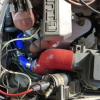
Hoses look like this:
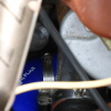
Here is one trouble spot: in order to get the elbows to fit, I had to cut it way back and there is barely enough straight tubing to get it on the turbo. It is on. We'll see how long it stays on. (I should add that the 55mm hose is a perfect fit.) You can just barely see how it barely fits on the turbo intake.
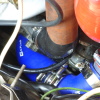
The other issue: the fit is TIGHT. There is going to be some rub on the firewall, maybe only on the one clamp, and the hose is touching the blow off valve hose. I'm guessing it will eventually rub through the silicone at this point.
Bit more cleaning up, getting the airbox sorted (I'm a bit tight with the thermostat housing; hoses need a trim) and then I should be ready to fire things up. Stay tuned for more excitement.