Ignition Switch Color Harness - help a colorblind brother out!
- stuartrubin
- Posts: 273
- Joined: Sun May 24, 2015 11:10 pm
- Your car is a: 1975 Fiat 124 Spider
- Location: 44122
Ignition Switch Color Harness - help a colorblind brother out!
I am in the process of replacing the ignition switch on my '75 Spider. The new switch is slightly different from the original one. These differences are well-documented in https://fiatspider.com/f15/viewtopic.php?t=37135, and other places.
One problem is that I am colorblind. My wife helped me identify some of the wires in the harness, but a few don't seem to match up with any of the documentation.
Apart from identifying the wires, there is also the issue that the new switch does not have the same number of pins for connection. From the installation instructions, it sounds like all three of the unidentified bundles (which per the documentation are "blue/black", "blue/pink", and the third bundle) should be connected together.
I believe one of these bundles is for the fuel pump for which there is no connection to the new switch.
Here is my harness:
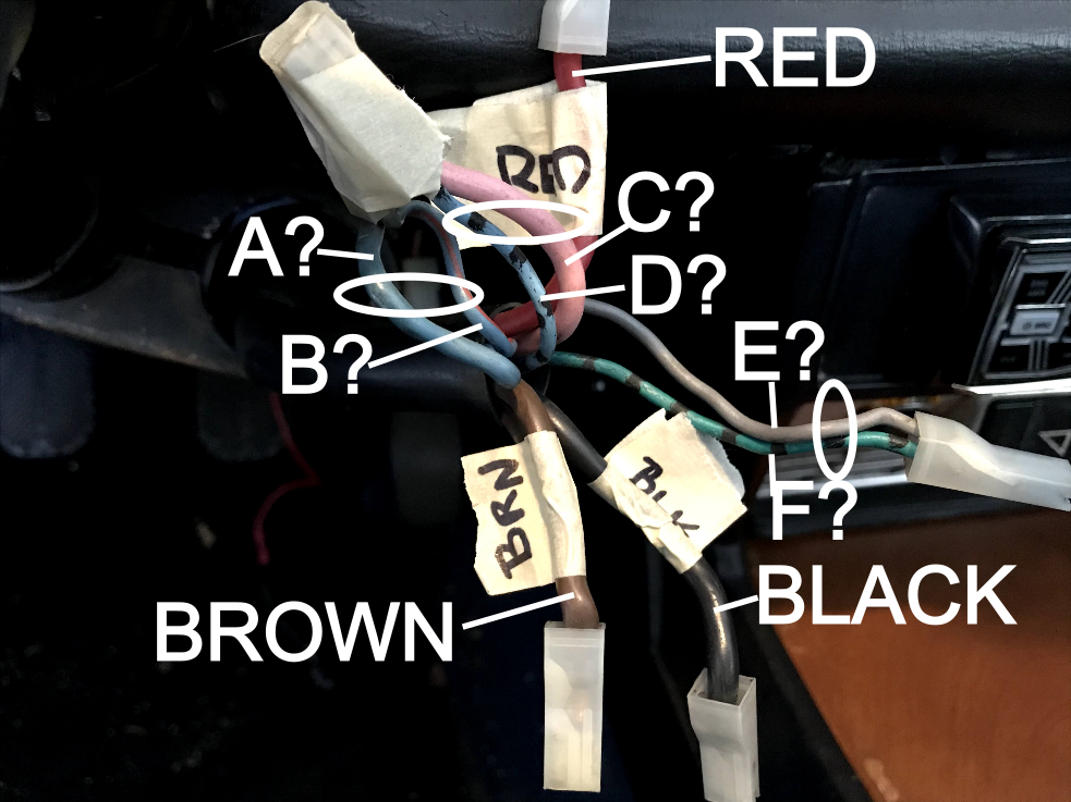
Can you please help me identify the colors and use for:
Bundle AB?
Bundle CD?
Bundle EF?
And should I really connect all six of the wires together and attach to connector #15 on the new switch?
FYI, the new switch is
https://www.midwest-bayless.com/p-10060 ... r-new.aspx
Thank you very much!
Stuart
Stuart
1975 FIAT 124 Spider
Il Mostro di Frankenstein
1975 FIAT 124 Spider
Il Mostro di Frankenstein
-
- Patron 2024
- Posts: 3015
- Joined: Fri Jan 27, 2006 11:45 pm
- Your car is a: 1981 Spider 2000
- Location: Wallingford,CT
Re: Ignition Switch Color Harness - help a colorblind brother out!
If your ignition switch is an original Sipea switch what is wrong that you are replacing it?
- stuartrubin
- Posts: 273
- Joined: Sun May 24, 2015 11:10 pm
- Your car is a: 1975 Fiat 124 Spider
- Location: 44122
Re: Ignition Switch Color Harness - help a colorblind brother out!
@spider2081, it is the original Sipea (I think). Starting was intermittent for a while (it would turn over but never actually start running), then would not start at all. Applying some pressure to the wiring harnesses would let it run.
In retrospect, I should have just started by inspecting the harnesses, but that ship has sailed...
Stuart
1975 FIAT 124 Spider
Il Mostro di Frankenstein
1975 FIAT 124 Spider
Il Mostro di Frankenstein
-
- Posts: 2130
- Joined: Wed Dec 24, 2014 10:21 pm
- Your car is a: 1978 124 Spider with Isuzu Turbo Diesel
Re: Ignition Switch Color Harness - help a colorblind brother out!
You may want to save the old switch especially if you do not add a relay to take the high load of the starter solenoid off the wiring harness and contacts inside it. A good number of folks here have found that a cleaned up OEM switch can be more reliable that many of the aftermarket alternates. The stater solenoid draws quite a bit taking its toll on the ignition switch however putting something as simple as a $10 lighting relay between the switch and the starter solenoid will greatly extend its life. Putting in that relay is one of the first modifications I would do on any Fiat set up like the 124.
- stuartrubin
- Posts: 273
- Joined: Sun May 24, 2015 11:10 pm
- Your car is a: 1975 Fiat 124 Spider
- Location: 44122
Re: Ignition Switch Color Harness - help a colorblind brother out!
I really like the relay suggestion. It's frustrating that FIAT did not design one in even in the 70's; they should have known about reliability issues. Nonetheless, in the short term, I'd just like to get the car back running with minimal effort. Once that's done, and I've confirmed that the root cause really is the starter switch, I'll consider the relay, maybe even with the original switch reconditioned back in place.
Until then, does anyone have an answer about connecting the three wire bundles (AB, CD, EF) together for the new switch?
Thank you!
Stuart
Until then, does anyone have an answer about connecting the three wire bundles (AB, CD, EF) together for the new switch?
Thank you!
Stuart
Stuart
1975 FIAT 124 Spider
Il Mostro di Frankenstein
1975 FIAT 124 Spider
Il Mostro di Frankenstein
-
- Patron 2024
- Posts: 3015
- Joined: Fri Jan 27, 2006 11:45 pm
- Your car is a: 1981 Spider 2000
- Location: Wallingford,CT
Re: Ignition Switch Color Harness - help a colorblind brother out!
I think your original ignition switch had a terminal #16. If you still have the switch could you check and see if it does and if it looks like it was used. I'm thinking you car might have an electric fuel pump that ran through an ignition control relay and a fuel pump relay. Problem is my wire diagram for a 1975 Spider and its device number index don't seem to match. Example the index shows item # 120 to be the electric fuel pump but I cant find it on the 1975 wire diagram. It is shown on the 76 diagram.
I believe the wires that were on terminal 16 of the Sipea ignition switch {green/black and gray/ - ) need to connect with the red wire on terminal # 50 (shown in the midwest photo) of the replacement switch. Also the terminal shown to have the Pink and blue/black wire in that photo also needs to have the Light blue and the light blue/red wires attached to it.
Terminals 50 & 16 have power on them in the "start position of the Sipea ignition switch
Terminals "INT and 15/54 have power on them when the ignition switch is in the "start" or run" positions of the Sipea ignition switch.
Hope this is some help
-
- Posts: 3799
- Joined: Fri Mar 15, 2019 11:23 pm
- Your car is a: 1969 and 1971 124 spiders
- Location: San Francisco Bay Area
Re: Ignition Switch Color Harness - help a colorblind brother out!
Stuart, sorry I'm late to the party here, but it sounds like you've gotten some good advice in the posts above. A few more thoughts from me regarding your colored wires and their function. Starting from the top of the picture:
1) The red wire goes to the starter solenoid. Putting 12 volts on that will engage the starter and cause the engine to turn over. It won't start without 12 volts going to the coil, though.
2) The pink and light blue/black stripe wires are connected together at the ignition switch. The light blue/black stripe wire goes to the B+ terminal on the ignition coil (see comment in #1 above). The pink wire goes to Fuse #9 (or "I") and is the power source for things like brake lights and a lot of the gauges and lights in the instrument cluster.
3) Light blue and light blue/red stripe. On my older cars, the light blue is a black wire which goes to the headlight toggle switch on the dash. The light blue/red stripe wire goes to Fuse #2 ("B") which is the heater blower and windshield wiper.
4) The infamous Brown wire. This goes to the starter motor connection that goes to the +12 on the battery, so the brown wire is an "always on" source of 12 volts for your ignition switch.
5) The large black wire goes to the alternator but then also directly to +12V on the battery, so it's another source of always on +12V.
The other wires (grey, blue/black stripe) that go off to the right, my guess is that those are for accessories like the radio, radio power antenna, etc. Just a guess of course.
Here is how things are connected in my earlier cars, so this might help with your '75:
Red wire goes to terminal 50 on the ignition switch.
Pink and blue/black wires go to terminal 15.
Light blue and light blue/red go to the "INT" terminal.
Brown wire goes to terminal 30.
Black wire goes to terminal 30/1.
Hope this helps.
-Bryan
- stuartrubin
- Posts: 273
- Joined: Sun May 24, 2015 11:10 pm
- Your car is a: 1975 Fiat 124 Spider
- Location: 44122
Re: Ignition Switch Color Harness - help a colorblind brother out!
Bryan, thank you very much for the explanation! I would like to correlate what you said to my annotations (since I don't do colors!)
Yours --> My Photo
1. Red --> Red
2. Pink --> C
2. Light blue/black stripe --> D
3. Light blue --> B
3. light blue/red stripe --> A
(Maybe A and B are reversed, but should not matter)
4. Brown --> Brown
5. Black --> Black
Mystery --> E
Mystery --> F
I have seen references to fuel pump wires going do the ignition switch. Could those be them?
So, the real question is: Can I connect A, B, C, D, E, and F all together?
Thanks again!
Stuart
Stuart
1975 FIAT 124 Spider
Il Mostro di Frankenstein
1975 FIAT 124 Spider
Il Mostro di Frankenstein
-
- Patron 2024
- Posts: 3015
- Joined: Fri Jan 27, 2006 11:45 pm
- Your car is a: 1981 Spider 2000
- Location: Wallingford,CT
Re: Ignition Switch Color Harness - help a colorblind brother out!
I think Stuart is trying to install an after market ignition switch he purchased from Midwest Bayless
https://www.midwest-bayless.com/p-10060 ... r-new.aspx opening the small photo on the page labeled 124 Spider shows their suggested installation. However it does not include all the wires that are connected to the 1975 Sipea ignition switch. I think the 1976 wire diagram may be more accurate than the 1975 wire diagram is. The 1976 shows the ignition switch terminal 16 as well as the electric fuel pump, fuel pump relay and ignition control relay.
Although the aftermarket switch terminals are identified similar to the Sipea some of them may function differently.
-
- Posts: 3799
- Joined: Fri Mar 15, 2019 11:23 pm
- Your car is a: 1969 and 1971 124 spiders
- Location: San Francisco Bay Area
Re: Ignition Switch Color Harness - help a colorblind brother out!
Stuart, my sincere apologies, as I did not take your statement about "colorblind" seriously enough. Sorry!stuartrubin wrote:So, the real question is: Can I connect A, B, C, D, E, and F all together?
I think your correlation of your wires and my explanation is correct, although I would label "A" as light blue and "B" as light blue/red stripe. As you said, they both connect to the same point, but they may carry different amounts of current and thus the correct installation may be necessary so as to not burn out some wires with too much current.
E and F? Those wires are mysteries to me, but they well could be to the electric fuel pump, or its associated relay.
OK, back to your question about connecting A-F together: It would probably work, although you may lose some of the original functionality or safety features. After all, there no doubt was a reason that these were separated in the original design. As the song goes (The Offspring), "Ya gotta keep 'em separated!" Sorry, I tend to reduce all challenges to a rock song somewhere...! It's just me.
-Bryan
-
- Patron 2024
- Posts: 3015
- Joined: Fri Jan 27, 2006 11:45 pm
- Your car is a: 1981 Spider 2000
- Location: Wallingford,CT
Re: Ignition Switch Color Harness - help a colorblind brother out!
Does your car have an original factory electric fuel pump installed? I think it would be located in the trunk between the fuel tank and the spare tire. If it does I believe the gray wire (your "E") and the green/black wire ( your "F" ) would connect with your Red wire. These 3 wires would connect to the red wire terminal (50) shown in the Midwest Bayless photo. Your letters A, B, C, and D would all connect to terminal 15 shown in the Midwest Bayless photo that shows only your "C" and "D" wires. The photo I'm referring to is the left small photo on the Midwest link in your original post.
- aj81spider
- Patron 2020
- Posts: 1526
- Joined: Fri Mar 11, 2011 9:04 am
- Your car is a: 1974 Fiat 124 Spider
- Location: Chelmsford, MA
Re: Ignition Switch Color Harness - help a colorblind brother out!
On my '74 the green/black goes to the fuel pump as mentioned. My 1975 wiring diagram is the hardest wiring diagram to read of all the years. However it shows an electric fuel pump and a green/black wiring going to it, so I'm guessing it's the same.
I've been wrong before, but I believe if you connect that to 50 with the red wire the fuel pump will only run when you are in start position. I think it needs to go to 15 with the rest of the wires.
Given how much load you have on one terminal with the new switch I think I would add some relays so the switch won't burn out. I have done that on my car and hope that my switch will now last forever.
A.J.
1974 Fiat 124 Spider
2006 Corvette
1981 Spider 2000 (sold 2013 - never should have sold that car)
1974 Fiat 124 Spider
2006 Corvette
1981 Spider 2000 (sold 2013 - never should have sold that car)
-
- Patron 2024
- Posts: 3015
- Joined: Fri Jan 27, 2006 11:45 pm
- Your car is a: 1981 Spider 2000
- Location: Wallingford,CT
Re: Ignition Switch Color Harness - help a colorblind brother out!
I could be wrong also, but I thought the carbureted Spiders had a fuel pump relay that was activated by the oil pressure switch that lights the low oil pressure warning light. When there is low on no oil pressure the oil pressure switch closes, lighting the light and energizing the fuel pump relay. When the fuel pump relay is energized it removes power from the fuel pump. These cars have a unique ignition switch that has a terminal 16. Terminal 16 only has power when the ignition switch is in the "start" position similar to terminal 50. Once thee car is started the power for the fuel pump is supplied through the fuel pump relay. This way the fuel pump shuts off when the engine is not running but the ignition switch is in the "run" position.
The aftermarket switch does not have 2 terminals that are powered in the "start" position.
- aj81spider
- Patron 2020
- Posts: 1526
- Joined: Fri Mar 11, 2011 9:04 am
- Your car is a: 1974 Fiat 124 Spider
- Location: Chelmsford, MA
Re: Ignition Switch Color Harness - help a colorblind brother out!
On my 1974 there is no fuel pump relay. You turn the switch to run and the fuel pump runs. I think this is factory, as my 1974 wiring diagram has no relay either.
The wiring diagram that I have for the 1975 (which is extremely hard to read - and for whose accuracy I cannot vouch) shows the ignition switch terminal 16 connected directly to the fuel pump as well.
I can only speak definitively for my car - but it seems that the ignition switch is connected directly to the fuel pump.
A.J.
1974 Fiat 124 Spider
2006 Corvette
1981 Spider 2000 (sold 2013 - never should have sold that car)
1974 Fiat 124 Spider
2006 Corvette
1981 Spider 2000 (sold 2013 - never should have sold that car)
-
- Patron 2024
- Posts: 3015
- Joined: Fri Jan 27, 2006 11:45 pm
- Your car is a: 1981 Spider 2000
- Location: Wallingford,CT
Re: Ignition Switch Color Harness - help a colorblind brother out!
Yes this is true.shows the ignition switch terminal 16 connected directly to the fuel pump as well.
I don't think Fiat and/or other publishers of Fiat Manuals are all in agreement and with out errors. I have never owned or a carbureted Fiat. I am looking at wire diagrams from Mirafiori.com and Clymer's shop manual for 1974, 1975 and 1976 Spiders. Both of these diagrams have an electric fuel pump. Both diagrams show 2 power sources for the pump. One directly from terminal 16 of the ignition switch (green/black wire} and the other from a relay. The relay in the Clymer diagram item # 128/3 identified as "fuel pump and ignition mode relay control switch" The wire diagram I downloaded has the relay identified as " Fuel pump relay"
As stated the diagrams are difficult to see/read.
Like all auto manufacturer's Fiat made mid year changes and I believe the publications probably illustrate either before the change or after the change but seldom both.
A number of Spiders with dual points have been modified to one set of points or electronic ignition. This could eliminated the ignition mode relay. and eliminate the safety aspect of the oil pressure being required for the fuel pump to run.
I have bench tested and serviced around 10 Sepia ignition switches that have a terminal 16, most do not. Terminal 16 connected to terminal 30 in the "start" position only on all the switches I tested.